Category Archives: General Information

General information about HVAC systems

Carrier Gas Furnace Part Identification

I have attached a PDF showing how we look up parts for a Carrier gas furnace. The product number I used is 383KAV036090ABJA. The 1st page is a significance chart showing what all the information in the product number means. It is critical we have the entire product number to identify parts required for repairs. We are able to go 1 step deeper than this PDF and identify parts that have been superceded to a new part number not listed on this sheet.

383KAV036090ABJA

Note: Many times there are added notes that are not published in this PDF. It is always the best practice to call or email us with the product number to identify the correct parts for your repair.

www.shortyshvac.com

Shortys HVAC Supplies 877-821-8770

parts@shortyshvac.com


Fall Furnace Tuneup

Cold weather is approaching so now is a good time to take a look at your furnace to be sure it is ready for winter. If you have a gas furnace check the inside of the flue pipe for any sign of soot. Soot indicates a potentially dangerous issue so if there is soot in the pipe be sure and have the furnace checked by a professional. Check the flue for any restrictions. If accessible birds will build nests in a flue pipe.

With the power off check the blower wheel for items that might have been sucked in and making the wheel out of balance. If belt driven check the belt for weathercracks and proper tension. Check the bearings in the motor and blower for any play. There should be be no play parallel to the shaft. In and out is okay. Up and down is not. Now is a very good time to change the air filters.

Next mix up some dish washing soap with water in a spray bottle and spray the gas pipe to be sure there are no gas leaks. Pay special attention to unions and gas cocks. Gas cocks are packed with grease and over time it hardens and cracks.

Next start the furnace and take a look at the flame. The furnace should have either end shot burners or ribbon burners. A ribbon burner is a long skinny burner that extends into the heat exchanger. The flame should be blue and very crisp with a well defined inner cone. The flame should not deviate when the blower is on and should not burn down around the burner.

The flame should also be blue on an end shot burner. An end shot burner is short and the flame burns at the end of the burner and extends through a flame retainer plate into a round tube. The flame should extend into the round tube heat exchanger and not roll out around the plate. It should not change when the blower comes on.

Pay attention to the draft inducer and make sure it is not noisy. Noise may indicate a potential bearing failure. If you have a 90% efficient furnace with PVC flue make sure the drain lines are clear and open.

Humidifier Tuneup

If you have a humidifier October/November is a good time to do maintenance. The water panel should be changed at least one time per year. Some humidifiers require more frequent replacement. Consult your owners manual for recommended change interval. Be sure and clean the water containment area. It is an ideal condition for bacterial growth. If you have respiratory problems consider the Honeywell brand water panels with Agion coating. They are slightly more expensive. They are treated to inhibit bacterial growth inside the humidifer and are available for most brands of humidifers.
Do not forget to check the strainer located in the water supply line. If it is clogged up the humidification process will be impeded.
Click on link below for humidification products.
http://shortyshvac.com/index.php?main_page=index&cPath=85

Refrigerant

Refrigerant has been called Freon for years because DuPont started manufacturing it under the brand Freon. The correct term is refrigerant. There are several different types of refrigerant and each has a specific pressure temperature chart. The different types of refrigerants boil at different temperature points and are used for different applications. Refrigerant pressures are measured in PSIG which is pounds per square inch gauge. This means that 0 PSIG is actual atmospheric pressure at sea level.

A property of refrigerant that makes it useful to cool a house or building is the ability to read the pressure of the refrigerant and know it’s temperature. Refrigerants will change from a liquid state to a vapor state at a very low temperature. If you control the pressure of the refrigerant you can control the temperature it changes state at.

For example, a drum of liquid R-22 at 80 degrees will change from a liquid to a gas and the pressure will increase as the gas expands. When the pressure reaches around 143 lbs, the boiling will stabilize and as long as the temperature remains constant the pressure will remain constant.

If the drum is moved to a cooler area the pressure will be affected. If the new area is 60 degrees the refrigerant gas will condense back to a liquid and the pressure will drop. When the pressure reaches around 102 lbs the condensing of the gas will stabilize.

If you connected a regulator to the R-22 refrigerant drum and allowed liquid refrigerant to pass through it into a coil and set the regulator at 58 lbs the coil temperature would be controlled to 32 degrees until you ran out of refrigerant. If you blew 75 degree air across the coil some heat in the air would be absorbed by the refrigerant and the air temperature would drop.

If we have a way to collect the refrigerant and put it back in the drum we would have a refrigeration system. This is accomplished with a compressor. When the refrigerant leaves the coil we were discussing it travels through a line as a low pressure vapor into a compressor that compresses the refrigerant into a high pressure vapor. When it is compressed the temperature will be much higher than the outdoor air temperature.

It then travels to a condenser coil as a high pressure superheated gas where it will be cooled by blowing ambient air across a coil. As the refrigerant gives up heat into the ambient air it will cool and condense to a high pressure liquid. This high pressure liquid will be metered through a metering device (much like the regulator we discussed earlier). As it passes through the metering device it will change to a low pressure liquid.

This drop in pressure will cause a drop in temperature of the liquid refrigerant. The low pressure liquid will travel to an evaporator coil and the temperature of the refrigerant will be less than the temperature of the air being blown across the coil. The refrigerant will absorb heat from the air causing the air temperature to drop and the refrigerant to boil and change to a low pressure vapor.

The low pressure vapor will become superheated and return to the compressor and the process will begin again.

Understanding Simple Thermostats

The basic terminals on a thermostat are R G Y and W. The wiring should be color coded R for red, G for green Y for yellow and W for white.

R is the terminal coming from the transformer that is powered all the time. The thermostat is actually a group of switches designed to energize different circuits. R is the main power source. The G terminal receives power from R and energizes the fan circuit when the fan switch is turned on. When the fan switch is in the automatic position G is connected to the Y terminal. Y is the terminal that is used to turn on the cooling circuit. The Y terminal is connected to the R terminal when the Heat/ Off / Cool switch is in the cool position and the temperature has risen above set point. This energizes the cooling circuit and the fan circuit.

The W terminal is used to energize the heating circuit. When the Heat/ Off/ Cool switch is in the heat position and the temperature has dropped below setpoint R terminal is connected to the W terminal and the heating circuit is energized. On a typical gas furnace the fan is energized from a temperature switch that senses the temperature of the heat exchanger or a timing mechanism in a circuit board that senses power on the W terminal.

Some thermostats have other terminals. The most common are RC and RH which are used if you have a system with seperate 24 volt power supplies for heating and cooling. If you have 1 power supply the RC and RH must be jumpered together. Another teminal is C. It is used to connect the other terminal on the transformer if this particular thermostat requires a common wire for operation. One other common terminal is O or B and is used to power the reversing valve for a heat pump. If you are using O or B you will most likely also have a terminal labeled W2. This terminal is used to energize the backup heating system for a heat pump and energizes  if the building temperature falls to far below setpoint.

HVAC Split System

A split system is designed with  separate outdoor unit for cooling and an indoor unit for heating. The indoor unit can be a gas furnace with an evaporator coil, an oil furnace with an evaporator coil or an air handler with built in evaporator coil and electric heating elements. The indoor unit usually supplies the airflow for the heating system and the cooling system.

The outdoor unit is called the condensing unit. It is connected to the evaporator coil by 2 copper lines. The small line supplies high pressure liquid refrigerant to the evaporator coil. The large line returns the low pressure refrigerant vapor back to the condensing unit. This line will be below ambient temperature and should be insulated.

Since the indoor unit is used for heating and cooling the air filter is used for both modes. Keeping the air filter clean is critical to the proper operation of the system.

HVAC Package Unit

A package unit is a self contained piece of equipment designed for roof mount or sidewall installation. The equipment contains the complete heating and cooling system and comes ready to connect the ductwork. Package units are configured with openings in the bottom panel and a side panel for connecting ductwork. The unit is delivered with covers installed in place over the duct connections and the correct set of covers will be removed for installation depending on if the unit is to be ducted through a curb or sidewall.

When mounted on a flat roof it is very common to install the unit on a roof curb. The curb is mounted to the roof and flashed to make it weather tight. The roofing and decking in the center of the curb are removed to gain access to the interior of the building. The curb is constructed to be the same size as the unit so the unit will sit squarely on top of  it. Cross pieces are installed at the top of the curb to match the duct connections on the bottom panel of the unit. The ductwork is fabricated to drop in from the top of the curb with a 1″ lip folded out to rest on the cross pieces. The top of the curb is thin covered with a 1″ foam strip acting as a gasket to seal in the air flow. The unit is then set in place on the curb and ready for field connections for electric, stat, and gas if used.

When used as a sidewall installation the unit will be installed on a pad or some type of stand. The ductwork will connect to a sidewall on the unit and a return and supply duct will be installed from the unit through a sidewall in the building to connect to the building duct system.

Contactors

Contactors are electromechanical switches that turn on the air conditioner compressor or electric heating elements. The critical ratings for a contactor are number of poles, coil voltage and contact amps. The coil voltage and contact amp ratings are typically marked on the tag of the contactor. The number of poles are actually the number of contacts or switches in the contactor.

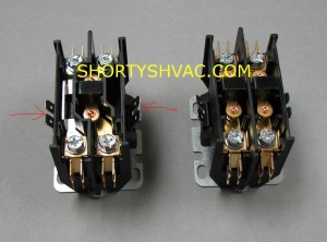
In the picture below the contactor on the left is a single pole. It is manufactured using the same housing as the contactor on the right which is a double pole. You can see the contactor on the left has 1 set of contact points. The points on the left have been replaced in the housing with a bar that connects the top and bottom connections together.  The contactor on the right has 2 distinct sets of contact points so it is considered a double pole.

The amp ratings for a contactor are given as FLA for a motor load and RES for an electric heat load. The RES ratings is usually somewhat higher.

The coil voltage is rated for the voltage of the control circuit which is generally 24 VAC with most air conditioning systems.  I have added 2 red lines in the picture for the contactor on the left showing the 24 VAC connections for the contactor. As you can see the contacts are clearly separated from the main power contacts. The operation of the contactor is 24 VAC is applied to the coil via a common wire from the transformer. The other side of the coil is powered by the R side of the circuit through the thermostat. This energizes the coil and the magnetic field of the coil pulls in the contacts so they touch to start power flowing for the load. Power wires will be connected to the 2 terminals on top of the contactor and the compressor wires will be connected to the 2 terminals on the bottom of the contactor. When the contacts touch the compressor should start. Note the power wires and compressor wires can be installed on the top or bottom of the contactor.  As long as they are wired properly the system should operate.

Contactor

Maintaining Your Air Conditioner For Cooling Season

Springtime is a good time of the year to do preventative maintenance on your air conditioning system. Taking care of small problems before it gets too warm may keep the equipment operating trouble free during the hot weather.

While you are performing these checks make sure the power has been disconnected.

Remove the cover over the unit electrical compartment and take a look at the wiring for any overheated or loose connections. All connections should be tight and the wiring should show no signs of discoloration. If the wiring is discolored that section of wiring should be replaced. Examine the contactor points looking for discoloration or pitting. Discoloration can indicate a bad connection when the points are energized. Also take a look at the capacitor for any signs of oil leakage. If the capacitor top is dome shaped or there is any sign of oil the capacitor should be replaced.

Check the condenser fan motor and make sure the blade turns freely. Also check the shaft for any side to side movement. If there is any side to side play in the motor the blade will turn free but the motor has worn bearings and does need to be replaced. The shaft will move in and out but it should not move side to side. Also look closely ate the fan blade. The individual blades are installed with rivets. The blades are usually aluminum and can stress crack around the rivets. If the blade is not changed it can tear and get caught in the coil. This can cause a tear in the copper tube and a loss of charge. If the blade does crack and break it will lead to a very expensive repair.

If you see any signs of an oil leak around any of the copper lines it indicates a refrigerant leak and we recommend getting this checked by a technician.

While you are looking at the motor is a good time to take a garden hose and wash out the outdoor coil. We do not recommend using chemicals to clean the coil as it can cause deterioration of the aluminum fins. Water should be sufficient for cleaning. Allow the unit to dry out for a few hours before restoring power.