The easiest way to replace a contactor for a do it yourself repair is to first make absolutely certain the power is turned off. Also make sure the air handler is shut off as the 24 volts to the contactor is powered from there. If the 24 volt circuit is left powered on you stand the chance of shorting out a control wire and burning out the 24 volt transformer. After you have verified all power is off remove the mounting screws and pull the old contactor out of the way without removing any wires if possible. If you must remove wiring make sure and mark the location the wire was connected to. Install the new contactor. Disconnect each wire and reconnect to the new contactor before removing the next wire. If you change one wire at a time you should not have any problems.
I have included a picture showing an old style contactor and a new style contactor. The new style has a dust cover over the contacts that is removable to inspect the contacts. The new style also has the 24 volt connections located on each side. The old style contactor does not have a dust cover over the contacts and the 24 volt connections are on the same side. I have drawn a red line beside the 24 volt connects for reference. The 24 volt connections are not polarity sensitive as the voltage is AC. It does not matter which connection the wires are placed on as long as both wires are not on the same connection.
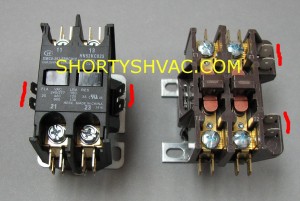
Contactors can be purchased for do it yourself repairs from Shortys HVAC Supplies. If you are not sure of the correct part number please call or email us at parts@shortyshvac.com and we will be happy to identify the correct part for you.
The most common use of transformers in furnace and air conditioner equipment is to step down the voltage to 24 VAC for the control circuit. Transformers have 3 ratings. Primary voltage which is the line voltage applied to the transformer primary winding, secondary voltage which is the 24 VAC control voltage induced in the secondary winding and the VA rating. The VA rating is the amount of power the transformer can supply without burning up the windings. VA stands for Volts X Amps which is the same formula for wattage. Many transformers are rated at 40 VA which means they are capable of sustain a load condition up to 1.6 A on the 24 V side.
Transformers have no moving parts. The only failure you should see with a transformer is caused by an overload condition such as a shorted wire or shorted control on the 24 VAC circuit causing an excessive amp draw. Sometimes a voltage spike such as a lightning strike will damage a transformer but it usually causes other damage.
Common failures are a bare spot on the wire caused by rubbing where it passes through an equipment sidewall, rodent damage in a crawl space or wall and wiring getting cut while trimming grass around the outdoor unit.
In the picture below you can see 2 different types of wiring for a transformer and how it is marked. The transformer on the right shows the 208 or 230 V connections on one side. The other side is marked load. The tag is marked PRI 208/230V SEC 24V 40VA. The transformer on the left has the connections marked on the tag. The tag reads PRI 120V BLK-WHT SEC 24V RED-BLUE 40VA. This designation means the primary is rated for 120VAC and connects using the black and white wire. The secondary is 24 VAC and connects using the red and blue wire.
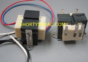
When you have a call for cooling from the thermostat the R terminal on the thermostat is connected internally to the terminal labeled G. The wire typically connected to the G terminal is green and it connects to the G terminal on the circuit board. When this terminal receives 24 V input from the thermostat it energizes a relay on the circuit board starting the indoor fan. At the same time R is connected to terminal G it also connects to the terminal labeled Y on the thermostat. This terminal is typically connected to a Yellow or Blue wire depending on what brand of thermostat wire was used during installation. This wire will connect to a terminal on the circuit board labeled Y. This terminal is only a junction point on the circuit board. It does not connect to anything internally on the board. There will be one other connection on the circuit board labeled C. This terminal is connected back to the common terminal on the 24 V side of the transformer and is placed there for connecting the 24 V power to the outdoor unit. When the thermostat calls for cooling 24 V power will be available at Y and C on the circuit board. There will be a separate thermostat wire bundle with a wire running from each of these terminals to a contactor coil in the outdoor unit.
On a basic gas furnace and air conditioning system the thermostat control circuit is a simple design. The transformer steps the line voltage down to 24 VAC. When you are checking this circuit the volt meter needs to be set up for AC not DC. The primary side of the transformer should have an input of 120 VAC. The secondary terminals should have an output of 24-28 VAC. If you do not have 120 VAC between the 2 primary terminals you will not have an output voltage. If you do have input voltage between the primary terminals and 0 volts between the secondary terminals the transformer has failed. This indicates an issue in the 24 V circuit that must be addressed. Otherwise the new transformer will fail as soon as power is applied. One of the secondary terminals on the transformer will be connected to one side of all of the operating devices such as contactors, relays, circuit boards. The other secondary terminal supplies the R terminal on the thermostat. The thermostat acts like a switch to turn everything on for operation.
When you have a call for heat the thermostat closes a switch connecting R from the transformer to W on the thermostat. This sends power through all the safety switches to the circuit board to start the fan and to the gas valve to light the burners. Common practice is to connect the red thermostat wire to R and the white thermostat wire to W. The circuit board has a time delay built in to allow the burner to start generating heat before starting the fan. When the thermostat reaches temperature and shuts off the gas valve another time delay is initiated to allow the fan to run and cool down the furnace. This is why we do not recommend aftermarket circuit boards. The timing has been determined by the manufacturer for optimum life and efficiency of the furnace and the algorithm is proprietary to the equipment manufacturer. Using a true OEM board can prevent premature failure of your equipment.
Amp readings are useful when checking the condition of a motor. In the picture below we are checking the amp draw of a functioning motor that is not giving us any problems. Note the clamp has been placed around one power wire feeding the motor. The thumbwheel was turned to AC Amps before placing the meter clamp around the wire. Always set your meter properly before connecting. This motor has a FLA (Full Load Amp) rating of .5 A If the motor is drawing more than that there is an issue that needs to be corrected. It could be bad bearings, bad capacitor, incorrect motor, incorrect fan blade, loose wiring. If the motor is drawing over the FLA the motor will overheat and shut off. This motor is drawing .4 A so it is in good operating condition.
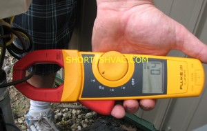
Electric meters are the best tool you can use to troubleshoot your furnace or air conditioner as most failures that the average do it yourself person attempts are of an electrical nature. When you purchase a meter I strongly recommend purchasing one with a CAT III 600 V rating. If a meter is connected incorrectly or not set in the correct mode it can explode. Cat III ratings mean the meter has fusing inside it to prevent meter damage and operator injuries. If it does inadvertently get connected incorrectly and the fuse blows it must be replaced with the specified fuse in order to maintain the safety of the meter. A cheaper meter has a very good chance of causing severe injuries to the novice.
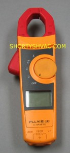
The picture listed below shows a Fluke 333 meter which is CAT III 600 V rated. The top of the meter is a clamp that spreads open and clamps back together for taking amp readings. There is a thumbwheel in the center of the meter for the different testing functions. Below the thumbwheel is a window where the readings are displayed. On the bottom of the meter are 2 ports. The left port is black and the right port is red. The ports are where the meter leads plug in for taking readings.
This meter can be used to read Alternating Current (AC) Amps, Ohms, Direct Current (DC) Volts and AC Volts.
A common basic air conditioning system and gas furnace application consists of a gas furnace located inside the building with an evaporator coil and a condensing unit located outside the building usually at ground level. The gas furnace blower is used to circulate the air over the evaporator coil where it is cooled and distributed through the building via the duct system. The gas furnace has a transformer inside the control panel that reduces the 120 volt power supplied to the furnace to 24 volts used for the control power. The 24 volts is sent to the thermostat where it is switched to turn equipment on and off as required by the temperature inside the building. On a call for cooling the thermostat has 2 circuits that are energized. It will supply control voltage back to some type of device that turns on the blower motor. It also supplies control voltage to the outdoor unit to energize it. These are two totally separate circuits so that gives you a clue during troubleshooting. If the indoor fan and the outdoor unit are both off you should suspect either a loss of 24 volts from the transformer or a bad thermostat or thermostat wire. If the outdoor unit is operating and the indoor fan is not you will need to troubleshoot the fan circuit. If the indoor fan is operating and the outdoor unit is not then most likely the issue is in the outdoor unit.
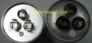
Run capacitors used in HVAC applications can be either round or oval shape. They also can be either a single or dual capacitor. A single capacitor has one set of plates and is used for the operation of one motor. A dual capacitor is actually two capacitors in one shell sharing a common plate. Dual capacitors are used for the operation of two motors. The two different type of capacitors can be differentiated by the terminals on top. A single capacitor will have two terminals and a dual capacitor will have three terminals on top. The two internal capacitors share a common plate for both motors labeled C on the top of the capacitor. The other terminals will be labeled FAN for the fan motor and HERM for the compressor. It is very important to make sure the wires go back on the same terminals when replacing a capacitor. A capacitor can fail and cause the fan motor and compressor not to start. The top of the capacitor should be perfectly flat. If it is slightly domed or has any type of oil leak it should be changed. Bad bearings in a fan motor can cause a capacitor to fail. Capacitor failures are very common during heat waves as excess heat does cause damage. Make sure power has been disconnected before making any repairs. In the picture below the capacitor on the right is slightly domed. Notice the flat top on the new capacitor on the left. Also notice the terminals are clearly marked.
Helping with Do It Yourself Funace and Air Conditioner Repairs


