Carrier Gas Furnace Part Identification

I have attached a PDF showing how we look up parts for a Carrier gas furnace. The product number I used is 383KAV036090ABJA. The 1st page is a significance chart showing what all the information in the product number means. It is critical we have the entire product number to identify parts required for repairs. We are able to go 1 step deeper than this PDF and identify parts that have been superceded to a new part number not listed on this sheet.

383KAV036090ABJA

Note: Many times there are added notes that are not published in this PDF. It is always the best practice to call or email us with the product number to identify the correct parts for your repair.

www.shortyshvac.com

Shortys HVAC Supplies 877-821-8770

parts@shortyshvac.com


Fall Furnace Tuneup

Cold weather is approaching so now is a good time to take a look at your furnace to be sure it is ready for winter. If you have a gas furnace check the inside of the flue pipe for any sign of soot. Soot indicates a potentially dangerous issue so if there is soot in the pipe be sure and have the furnace checked by a professional. Check the flue for any restrictions. If accessible birds will build nests in a flue pipe.

With the power off check the blower wheel for items that might have been sucked in and making the wheel out of balance. If belt driven check the belt for weathercracks and proper tension. Check the bearings in the motor and blower for any play. There should be be no play parallel to the shaft. In and out is okay. Up and down is not. Now is a very good time to change the air filters.

Next mix up some dish washing soap with water in a spray bottle and spray the gas pipe to be sure there are no gas leaks. Pay special attention to unions and gas cocks. Gas cocks are packed with grease and over time it hardens and cracks.

Next start the furnace and take a look at the flame. The furnace should have either end shot burners or ribbon burners. A ribbon burner is a long skinny burner that extends into the heat exchanger. The flame should be blue and very crisp with a well defined inner cone. The flame should not deviate when the blower is on and should not burn down around the burner.

The flame should also be blue on an end shot burner. An end shot burner is short and the flame burns at the end of the burner and extends through a flame retainer plate into a round tube. The flame should extend into the round tube heat exchanger and not roll out around the plate. It should not change when the blower comes on.

Pay attention to the draft inducer and make sure it is not noisy. Noise may indicate a potential bearing failure. If you have a 90% efficient furnace with PVC flue make sure the drain lines are clear and open.

Humidifier Tuneup

If you have a humidifier October/November is a good time to do maintenance. The water panel should be changed at least one time per year. Some humidifiers require more frequent replacement. Consult your owners manual for recommended change interval. Be sure and clean the water containment area. It is an ideal condition for bacterial growth. If you have respiratory problems consider the Honeywell brand water panels with Agion coating. They are slightly more expensive. They are treated to inhibit bacterial growth inside the humidifer and are available for most brands of humidifers.
Do not forget to check the strainer located in the water supply line. If it is clogged up the humidification process will be impeded.
Click on link below for humidification products.
http://shortyshvac.com/index.php?main_page=index&cPath=85

Refrigerant

Refrigerant has been called Freon for years because DuPont started manufacturing it under the brand Freon. The correct term is refrigerant. There are several different types of refrigerant and each has a specific pressure temperature chart. The different types of refrigerants boil at different temperature points and are used for different applications. Refrigerant pressures are measured in PSIG which is pounds per square inch gauge. This means that 0 PSIG is actual atmospheric pressure at sea level.

A property of refrigerant that makes it useful to cool a house or building is the ability to read the pressure of the refrigerant and know it’s temperature. Refrigerants will change from a liquid state to a vapor state at a very low temperature. If you control the pressure of the refrigerant you can control the temperature it changes state at.

For example, a drum of liquid R-22 at 80 degrees will change from a liquid to a gas and the pressure will increase as the gas expands. When the pressure reaches around 143 lbs, the boiling will stabilize and as long as the temperature remains constant the pressure will remain constant.

If the drum is moved to a cooler area the pressure will be affected. If the new area is 60 degrees the refrigerant gas will condense back to a liquid and the pressure will drop. When the pressure reaches around 102 lbs the condensing of the gas will stabilize.

If you connected a regulator to the R-22 refrigerant drum and allowed liquid refrigerant to pass through it into a coil and set the regulator at 58 lbs the coil temperature would be controlled to 32 degrees until you ran out of refrigerant. If you blew 75 degree air across the coil some heat in the air would be absorbed by the refrigerant and the air temperature would drop.

If we have a way to collect the refrigerant and put it back in the drum we would have a refrigeration system. This is accomplished with a compressor. When the refrigerant leaves the coil we were discussing it travels through a line as a low pressure vapor into a compressor that compresses the refrigerant into a high pressure vapor. When it is compressed the temperature will be much higher than the outdoor air temperature.

It then travels to a condenser coil as a high pressure superheated gas where it will be cooled by blowing ambient air across a coil. As the refrigerant gives up heat into the ambient air it will cool and condense to a high pressure liquid. This high pressure liquid will be metered through a metering device (much like the regulator we discussed earlier). As it passes through the metering device it will change to a low pressure liquid.

This drop in pressure will cause a drop in temperature of the liquid refrigerant. The low pressure liquid will travel to an evaporator coil and the temperature of the refrigerant will be less than the temperature of the air being blown across the coil. The refrigerant will absorb heat from the air causing the air temperature to drop and the refrigerant to boil and change to a low pressure vapor.

The low pressure vapor will become superheated and return to the compressor and the process will begin again.

Understanding Simple Thermostats

The basic terminals on a thermostat are R G Y and W. The wiring should be color coded R for red, G for green Y for yellow and W for white.

R is the terminal coming from the transformer that is powered all the time. The thermostat is actually a group of switches designed to energize different circuits. R is the main power source. The G terminal receives power from R and energizes the fan circuit when the fan switch is turned on. When the fan switch is in the automatic position G is connected to the Y terminal. Y is the terminal that is used to turn on the cooling circuit. The Y terminal is connected to the R terminal when the Heat/ Off / Cool switch is in the cool position and the temperature has risen above set point. This energizes the cooling circuit and the fan circuit.

The W terminal is used to energize the heating circuit. When the Heat/ Off/ Cool switch is in the heat position and the temperature has dropped below setpoint R terminal is connected to the W terminal and the heating circuit is energized. On a typical gas furnace the fan is energized from a temperature switch that senses the temperature of the heat exchanger or a timing mechanism in a circuit board that senses power on the W terminal.

Some thermostats have other terminals. The most common are RC and RH which are used if you have a system with seperate 24 volt power supplies for heating and cooling. If you have 1 power supply the RC and RH must be jumpered together. Another teminal is C. It is used to connect the other terminal on the transformer if this particular thermostat requires a common wire for operation. One other common terminal is O or B and is used to power the reversing valve for a heat pump. If you are using O or B you will most likely also have a terminal labeled W2. This terminal is used to energize the backup heating system for a heat pump and energizes  if the building temperature falls to far below setpoint.

Changing Heat Pump Defrost Board

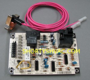
When changing the defrost circuit board it is a good idea to also change the defrost temperature sensor. The parts can be identified by providing the heat pump brand and model number. Always use the correct factory parts for this repair.

Make sure the power is disconnected for the outdoor unit as well as the inside air handler. The low voltage to the board is supplied from the transformer in the air handler and damage may result to the control system if control power is left on. Remove the old circuit board leaving the wiring intact. Install new defrost circuit board. Reconnect wires one at a time and reconnect on the same terminals for the new board. If there are any changes in the style of the board pay close attention to terminal markings and read any instructions provided.

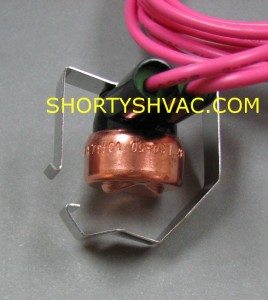
The defrost sensor is strapped on a lower copper connection on the outdoor coil near the small refrigerant line that goes towards the air handler. It has 2 wires that connect on 2 terminals of the defrost board. The strap around the copper line has an overlap retaining clip that holds the sensor on the copper. I have added a picture showing overlap retaining clip open. Remove the old sensor and install the new sensor. Disconnect old sensor from defrost board and reconnect new sensor.

Defrost_board

Defrost_sensor

Replacing the Condenser Fan Blade

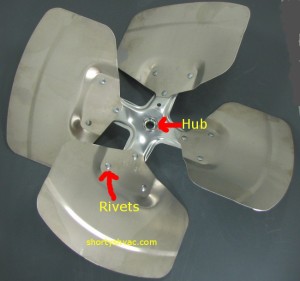
The condenser fan blade should be examined for signs of stress cracks. The most common place for the blade to develop stress cracks is around the rivets where the blades are attached to the hub. The blades are usually made out of aluminum and can flex during operation. If you see a hair line crack extending out from the rivet the blade should be replaced before the crack extends. The blade may flex and hit a bracket or copper line and can gouge a hole in the copper leading to a very expensive repair.

Another failure issue is the blade slipping on the hub. When this occurs sometimes the blade will make a high pitched whine during operation due to the blade turning slightly slower than the motor.

When you are replacing the fan blade make sure power has been disconnected from unit. Remove unit top and turn upside down for access to the blade. Remove lock screw in blade hub and soak hub with penetrating oil. Sand off any rust on the motor shaft. Hold the motor shaft between the fan blade hub and motor with a pair of pliers and gently rotate the blade on the shaft. Pull the hub away from the motor while rotating the blade on the shaft. When installing the new blade make sure the locking screw is tightened down on the flat spot on the shaft. this is very important.

LA01AA014_LRG

Cleaning the Condenser Coil

Cleaning the condenser coil is very important maintenance. As the coil gets dirty you lose system efficiency which over works the unit and drives up operating cost as well as causing excessive wear.  High operating temperatures can cause a breakdown of the compressor oil. Excessive high pressure can damage internal parts inside the compressor. Once the damage occurs it is a very expensive repair.

To clean the coil make sure all power is shut off to the unit including the 24 volt supplied from the air handler inside the building. Remove the fan assembly and wash the coil from the inside out with a garden hose. Do not use excessive pressure as this can damage the aluminum fins. We do not recommend using chemicals as some detergents will cause deterioration of the aluminum fins.

After washing out the coil re-assemble the unit and leave it off for 2-3 hours to give everything time to dry out before restarting the system.

Capacitor replacement

Another easy do it yourself repair is replacing the run capacitor. The most common type of capacitor today is the round style dual capacitor. Capacitors are susceptible to damage from heat and we do see many failures related to high summer temperature as well as motor issues. When changing the capacitor you must choose the proper size. The capacitor is rated for the fan motor and the compressor. Fan motors are used with different compressor combinations so the motor alone can not be used to identify the correct capacitor.

The capacitor is located in the electrical compartment of the unit and is usually round and resembles a coke can with wire terminals on top.

To replace the capacitor make sure the power is off to the unit. Verify the power is off. the capacitor will have a strap holding it in place. Remove the screw and install the strap on the new capacitor and secure the screw.  Note the color of the wire and carefully identify which terminal the wire is located on. The terminals will be labeled C  HERM and F or FAN on the old and new capacitor. Remove the brown wire from the F or FAN terminal and install on the F or FAN terminal on the new capacitor. Remove the wire or wires from the HERM terminal of the old capacitor and install on the HERM terminal of the new capacitor. Remove the wire or wires from the C terminal of the old capacitor and install on the C terminal of the new capacitor.


Helping with Do It Yourself Funace and Air Conditioner Repairs